
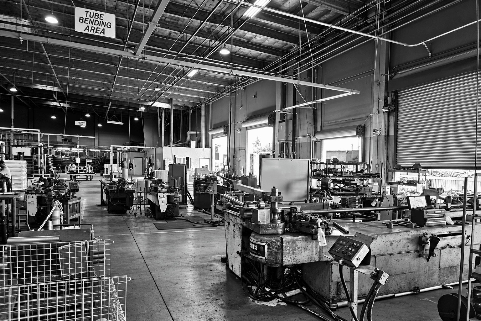
MANDREL TUBE BENDING
Defined bends. Practical manufacturing.
From first article through production.
SUPPORTING THE TUBE
THROUGH THE BEND
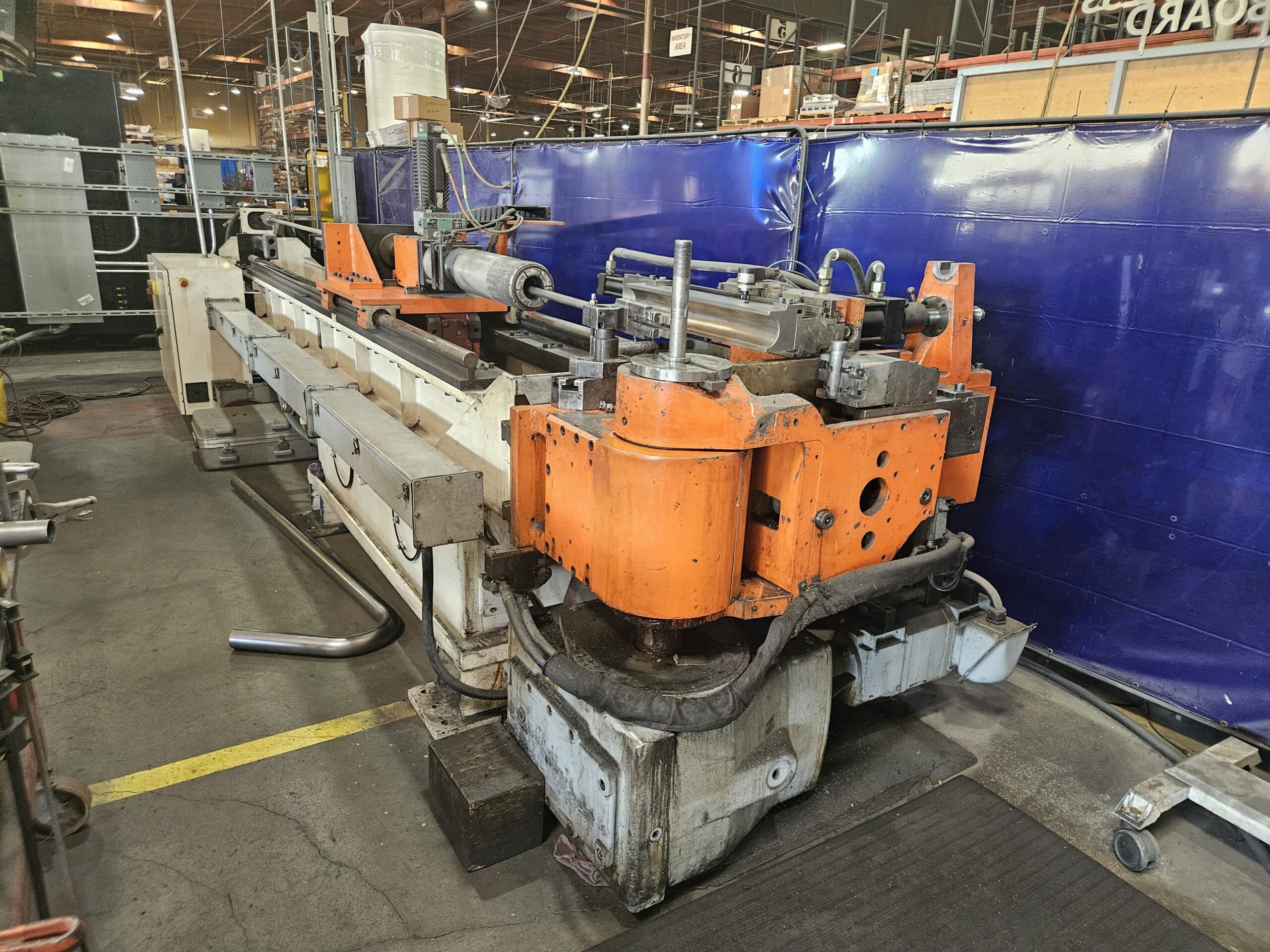
In mandrel-assisted rotary draw bending, the tube is drawn around a bend die while internal tooling helps support its shape.
It is a useful approach for defined bends where radius, angle and fit matter to the finished assembly.
Mandrel support does not mean zero flattening or zero wall change. The material, tube dimensions, tooling and finished-part requirements still matter.
UNDERSTANDING CENTERLINE RADIUS (CLR)
Centerline radius is the distance from the center of a bend’s arc to the centerline of the tube. It describes how tightly the tube turns. It is measured to the middle of the tube, rather than its inside or outside surface.
Radius is often expressed as a multiple of the tube’s outside diameter (OD): D of bend = CLR ÷ tube OD. A 3-inch OD tube with a 4.5-inch CLR has a 1.5D bend. A 1D bend has a CLR equal to the tube OD; the D value describes radius, while the bend angle describes how far the tube turns.
For that 3-inch OD, 4.5-inch CLR example, the nominal inside radius is 3 inches and the outside radius is 6 inches. These dimensions help explain why CLR alone does not describe the space occupied by a bend.
A smaller CLR relative to OD creates a tighter bend and increases the forming challenge. Wall thickness, material and tooling influence the support needed and the achievable result. A radius designation alone does not establish whether a particular tube can be bent successfully.
Show the required CLR and bend angle on your drawing, along with OD, wall thickness, material and straight lengths. If clearance is driving the design, include the available space and critical connections so we can review the geometry and tooling together.
MANDREL VS ROLL BENDING
PTB specializes in mandrel tube bending. We do not offer roll bending. The comparison below explains how the two processes differ.
Mandrel-assisted rotary draw
The tube is drawn around a bend die. Internal mandrel tooling helps support the tube through a defined bend.
Radius, angle, straight sections and the relationship between bends belong in the drawing review.
Roll bending
Rollers progressively form the tube into a curve, commonly for larger-radius sweeps.
It solves a different geometry problem. The material and finished-part requirements guide the process choice.
For mandrel tube bending, show us the route and critical dimensions so we can review the requirements for your part.
START WITH WHAT
THE PART NEEDS TO DO
PTB works on mandrel tube bending from first article through production. Send the details you have so we can review the part and tooling requirements.
- Material designation and condition
- Tube outside diameter and wall thickness
- Bend angles and centerline radii
- Straight sections and end requirements
- Bend orientation and critical fit points
- Quantity and repeat-production needs
- Current drawing revision and model, if available
- Inspection and documentation requirements
For a multi-bend part, show how the bends are rotated relative to each other. If the route is not final, explain the space and connections you’re working around.
REQUEST A QUOTE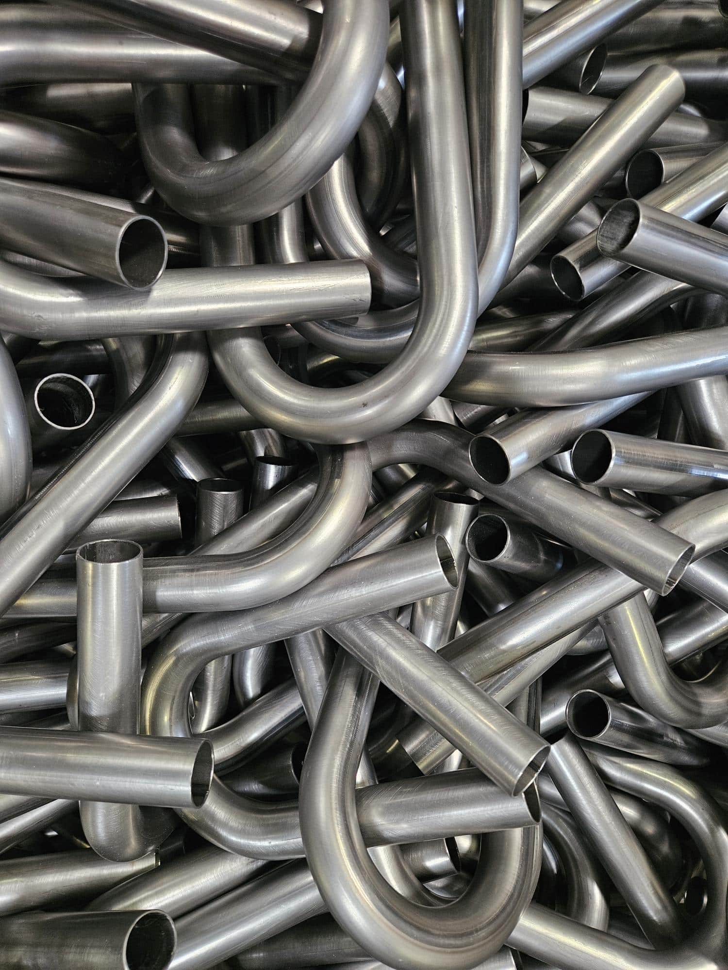
CATALOG PART
OR CUSTOM WORK?
Our catalog includes bends in aluminum, mild steel and stainless steel; available combinations depend on the actual listing.
Custom work is reviewed against the part and tooling requirements. Tell us what the tube needs to do, and we’ll work through the manufacturing route with you.